Engine Bleed Air System leaks can lead to unscheduled maintenance with operational interruptions, as well as to severe events such as in-flight turn-back or diversion due to loss of cabin pressurisation capability.
However, bleed leaks can be difficult to detect and localise - and time-consuming to troubleshoot. By using an air leak detector camera to locate leaks on the engine/APU bleed air system, operators can significantly reduce both Operational Interruptions (OI) and maintenance costs.
An overview of the Engine Bleed Air System
The Engine Bleed Air System is a sub-system of the Bleed Air System that is installed directly within the aircraft engine. It allows air to be bled from several engine ports in order to ensure sufficient pressurised air is provided to systems consumers which include:
- Engine starting (including cross starting)
- Wing anti-ice system
- Cabin pressurisation
- Fuel Tank Inerting System (FTIS)
- Cabin air generation and cooling systems (ATA21)
- Pressurisation of hydraulic tank, as well as waste and water storage tanks
Initially, introducing design enhancements to the overheat detection system (OHDS) on newer aircraft programmes helped to better find leaks. However, given the impact of bleed systems on operational reliability, another solution was required to go further and make it easier to localise a leak.
Leaks in the bleed system (ATA36) generally happen at bleed duct unions all along the duct network. Causes can include improper installation of the ducts or clamp, degradation due to bleed component ageing or a defective seal, improper maintenance.
How leaks can be detected
Mechanics can use soapy water, aluminium foil or temperature indicator strip to identify a leak on the bleed system. Each of these solutions presents disadvantages such as being inaccurate or being time-consuming.
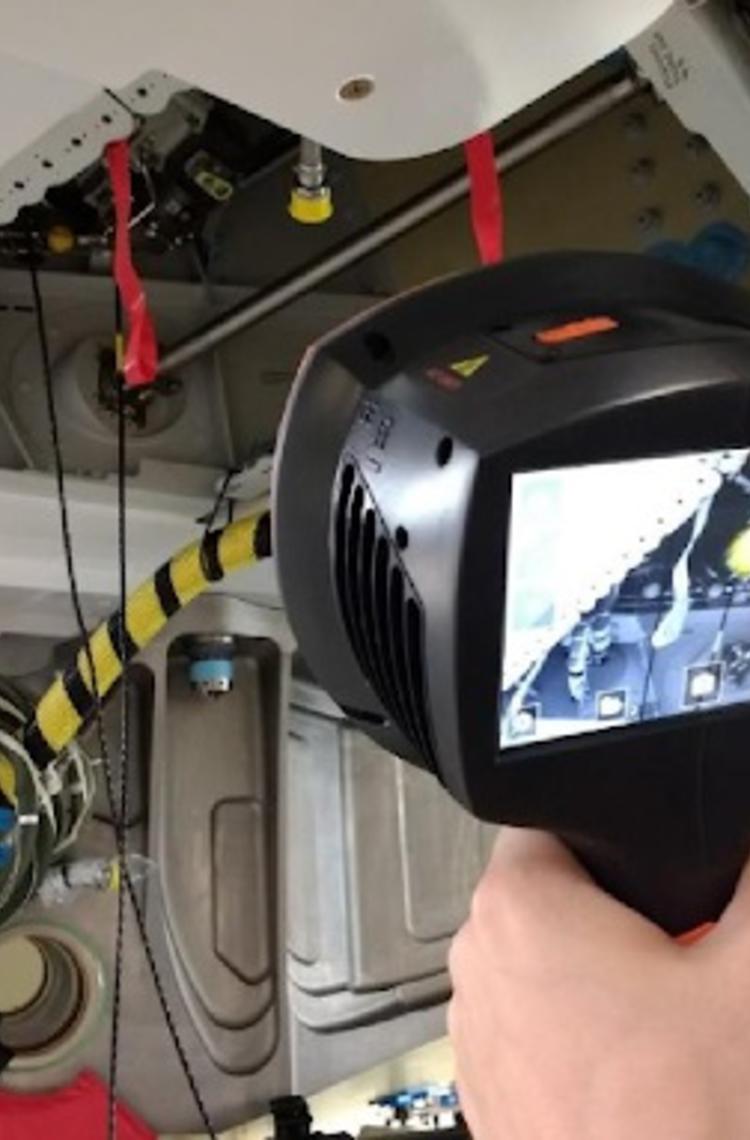
The leak detector camera (P/N 99V36009001000) allows quick leak detections in a safe environment; the mechanic does not have any direct contact with the bleed ductings which can be hot when pressurised by ENG or APU. It can detect any air leak independently of being hot or not with better reliability than current techniques. It is able to locate ultrasonic sound sources which are the typical signs of the air leak.
The camera uses 124 microphones to form a very precise acoustic image in the desired direction. This acoustic image is transposed in real-time on top of a digital camera picture, which allows the user, typically the mechanic, to accurately see from which directions the sound is coming from.
This tool camera is much more sensitive and accurate than our own ears, which means that it can locate sound sources that are inaudible to us, as well as sound sources that the human ear cannot reliably locate. It comes with a frequency range that extends to ultrasonic frequencies, particularly useful given that many leak phenomena can be precisely located using ultrasound.
The mechanics can also use the camera to do a quantitative test, which is more specific than current qualitative bubble or aluminium foil tests.
The defect report generated includes photos of the leak, and the aircraft data entered by the mechanic at the start of the process. The report can then be extracted in pdf format for further analysis or filing.
Aircraft applicability and availability
The tool can be used with all Airbus aircraft. It comes with a user-guide, is easy to use and requires no specific training.
Interested parties can contact maint.gsetools@airbus.com or send a TechRequest to the team SEMSB_GSETOOLS FRONT DESK.
Best practices
Preventive maintenance on the Engine Bleed Air System enables operators to schedule engine bleed air maintenance and increase operational reliability of the system.
Read FAST article 2018: Engine Bleed Air System - preventive maintenance
Locating leaks takes time and incurs costs. There are different manual ways to detect leaks. However, using ultrasonic sound technology, the bleed air leak camera tool makes the task faster and easier for mechanics, and provides immediate and precise acoustic images.
Your media contacts
Contact us
Arnaud RUBIO
GSE & Tools Engineering Domain Leader
