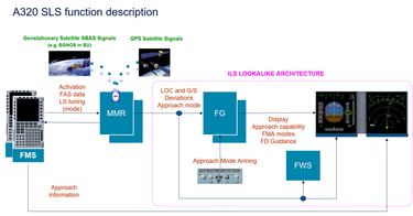
Thanks to global navigation satellite systems (GNSS) including GPS, aircraft navigation has significantly evolved over the past 25 years. Even if *ILS (Instrument Landing System) remains the primary means for precision approaches, new satellite navigation technologies are now in place to perform approaches. Airbus has integrated these new technologies with an ILS look-alike interface which benefits from the ILS operational experience. The most recent of these to be rolled out is a new certified cockpit avionics function for operators of the A320 and A330 families, for line-fit and retrofit – referred to as a satellite-based/augmented landing system (SLS).
This function enables pilots to perform ‘straight-in’ approaches using satellite positioning into airports, even in low-visibility conditions. SLS first entered service in Europe with the A350 in 2015 after Airbus pioneered its development and introduction for *CAT1 approaches with the support of the EU Agency for the Space Programme (EuSPA), formerly known as the European GNSS Agency (GSA), and the European Commission. SLS is also available on the A220 Family and will be soon offered on the A380.
Facilitating precision approach access to secondary airports
SLS capability enhances the airlines’ operations by enabling stable approaches especially at airports currently not having precision approach means; at main runways as a backup to ILS (e.g. during maintenance), or at alternate airports in case of diversion.
Mathieu Hialé-Guilhamou Engineering Navigation Specialist explains: “It is often the ‘secondary airports’ which are less likely to have sufficient throughput of traffic to justify the cost of installing radio-based ILS equipment on the ground. By contrast, ILS is usually present at primary airports to allow precision tracking of the glidepath down to the runway decision height, and is especially useful in bad weather or when there are obstacles below the approach. Now, with the combination of SLS capability in the aircraft and SBAS augmentation coverage in the sky, the aircraft is able to perform accurate ILS-like CAT1 approaches in low-visibility conditions into the secondary airports too.”
Pilot-friendly ILS-like display symbology
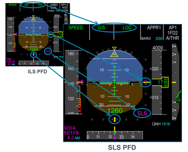
Since the SLS function design was fully integrated into the cockpit display architecture it was possible to make it very pilot friendly. The result is that with SLS pilots don’t have to change the way they fly the aircraft because the guidance symbology presented in the cockpit (on the “Primary Flight Display” – the PFD) looks just the same as what they are already used to for an ILS approach. In particular, the lateral and vertical magenta moving chevrons (below and to the side of the pilot’s attitude indicator respectively) are identical to the ILS equivalent – see PFD illustration below. In addition, along the top of the PFD and during an SLS approach, pilots will see the same familiar guidance modes “G/S” (vertical ‘Glide Slope’) and “LOC” (horizontal ‘Localiser’) status indications – in blue when armed or green when active.
In fact, there are other optional landing systems available for Airbus operators (which are beyond the scope of this article to describe individually) but which provide the same magenta lateral and vertical symbology for pilots, as well as the familiar LOC and G/S notifications on the PFD. These include: GBAS Landing System (GLS) and FMS Landing System (FLS) for non-precision approaches (e.g. using VOR, DME, NDB and LOC only). Since they are presented in the same way to pilots, they form collectively a group called “xLS”.
Positioning augmented by SBAS overlay satellites
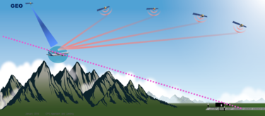
Through the aircraft’s GPS antenna, its multi-mode receiver (*MMR) receives data from GPS satellites, known in this aviation context as the “Global Navigation Satellite System” (GNSS). In addition to those positioning sources, the MMR also receives overlay corrections from “Satellite-Based Augmentation Systems” (SBAS), which transmit their signal via Geostationary Satellites. One of the reasons that the corrections are needed for accurate approaches is to counter possible ionosphere-induced position errors. Another reason is to continuously monitor and confirm the overall integrity of the GPS signal.
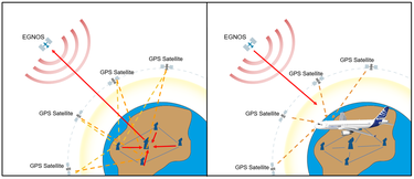

SBAS - EGNOS
Diagram showing GPS and SBAS satellite constellation architecture. The red arrow is on the left, the measurement of error over a continent by ground stations, and the sending by a master ground station to a geostationary satellite. On the right the geostationary satellite sends back the GPS correction to users, like an SBAS receiver-equipped aircraft.
The aircraft’s MMR also computes in real-time the accurate horizontal and vertical guidance which can be streamed to the electronic flight displays and autopilot. Moreover, this allows the autopilot to guide the aircraft along the computed reference trajectory, which can be monitored on the pilots’ displays.
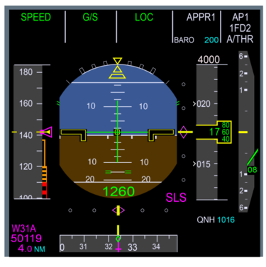
Alternatively the pilot can ‘hand-fly’ the aircraft by following the magenta lateral and vertical SLS-generated guidance chevrons (see diagram below). In this way SLS provides the aircraft with real-time precise satellite-augmented position information to provide either the human pilot or the auto-pilot with guidance in both the lateral and vertical axes. This is known to flight crews as “Localizer Performance with geometrical Vertical guidance” (LPV).
SLS approaches avoid reliance on barometric altitude or radio-based ILS
“An *RNP approach (*RNP APCH) to LPV minima (ie. using SLS) has the advantage of not relying on conventional barometric altitude nor temperature calibration. This contrasts with today’s *RNP approaches which use *LNAV/VNAV, as well as conventional “non-precision approaches” which are affected by variations in barometric altitude and temperature,” notes Hialé-Guilhamou.
“Fortunately with SLS, since its vertical guidance is no longer barometric but geometric, and regardless of the meteorological conditions, the aircraft’s final approach segment is always at the same position in space. This is a huge benefit, which directly categorises an LPV approach as “precision approaches equivalent”, down to CAT1 minima,” he adds.
Pilots have commented that the digital SLS satellite-based data can be more resilient than a CAT1 ILS analogue radio signal – because with SLS, the aircraft’s position relative to the trajectory is always available. Whereas with ILS, being terrestrial and radio-based, it can sometimes be susceptible to false localiser (denoted by ‘LOC’ on the PFD) or the glideslope (denoted by ‘G/S’) side lobes as well as interference affecting the ILS ‘protected area’. Nevertheless, VHF-radio based ILS remains, for the time being, the only certified means for a commercial airliner to perform a CAT2 approach or a CAT3B ‘auto-land’ onto the runway and subsequent rollout.
Prerequisites / enablers for SBAS
While the operation is largely seamless for the pilots, behind the scenes a variety of enablers had to be created in order for SLS to exist. These include:
Upgraded avionics on board the aircraft. These need to embody the new functions to support SLS. These avionics include: “Multi-Mode Receiver” (MMR) – which hosts the SLS function; the Flight Management System (FMS) – which hosts in its navigation database each discrete SLS procedure on a per-runway/airport basis; the Flight Warning Computer (FWC) and the autopilot (AP). To date the Honeywell FMS has been certified for use with the SBAS function, while the Thales FMS option is planned to be ready for the introduction of the A321XLR.
Global Navigation Satellite System (GNSS) coverage. These are civilian-controlled space satellite constellations providing positioning and timing data. Examples of GNSS include Europe’s Galileo, the USA’s NAVSTAR Global Positioning System (GPS), and China’s BeiDou Navigation Satellite System. Today all Airbus aircraft are equipped to use the GPS constellation for positioning and navigation.
Satellite-Based Augmentation Systems (SBAS) coverage, such as the “European Geostationary Navigation Overlay Service” (EGNOS). SBAS satellites improve the accuracy and reliability of GNSS information by correcting any ionosphere-induced signal errors and by providing information about the integrity of its signals. For US airspace the SBAS augmentation is provided by the “Wide-Area Augmentation System” (WAAS) and in India by “GPS Aided GEO Augmented Navigation” (GAGAN). Other SBAS satellites are being deployed in Japan, Australia/New Zealand and China, and also being developed for South Korea and Africa.
“Until very recently, SBAS has been widely used in commercial aviation to support “Area Navigation” for en-route lateral navigation in lieu of traditional ground-based Secondary Surveillance Radar (SSR) beacons, especially in the United States,” explains Hialé-Guilhamou. “This is to provide more accurate and available position data to the Air Traffic Controller, through the ADS-B (Automatic Dependant Surveillance - Broadcast) technology – mandated in the US from 2020. And for Europe, with SLS already operational with the A350 and A220 and now also entering service with A320 Family operators – starting in May 2022 with easyJet – Airbus, the EU and its partners are taking SBAS to the next level to provide vertical guidance for approaches down to CAT1 / 200 feet minima.”
Global uptake of SLS and LPV approaches
For any given airport runway, there needs to be a tailored SLS / LPV approach procedure in place if an operator wishes to perform an SLS approach there. Moreover, this tailored LPV procedure first needs to be assessed, designed, approved by the local aviation authorities, documented/published, and also pre-programmed into the aircraft FMS approach database – before any aircraft can perform an SLS landing. The uptake of such approved LPV approaches is rapidly increasing worldwide. In the USA LPV availability is particularly strong: As of March 2022 there were more than 4,100 LPVs serving almost 2,000 airports. This was helped by the fact that the US continent enjoys almost unbroken WAAS/SBAS satellite augmentation coverage from coast-to-coast.
Meanwhile, in Europe, as of May 2022, there are 750 operational LPV procedures with another 500 planned in the short/mid-term.
“With these and other parallel advances, SLS CAT1 approaches with LPV are therefore likely to become the norm across the European Union by 2030, taking precedence over ILS Cat 1 operations,” says Hialé-Guilhamou. “This is underscored by the European Commission’s publication in 2018 of an “implementing regulation” which lays down airspace usage requirements for Air Navigation Service providers, to provide services for all operations based on “performance-based navigation” (PBN), ie. using satellite navigation, except for Cat 2 and Cat 3 precision approaches – which will continue to use ILS.”
A short history of SBAS…
SBAS was originally developed in the US to support its Wide Area Augmentation System (WAAS) programme. WAAS was introduced in the USA in the early 2000's primarily to provide for the needs of general aviation. “At that time, the focus did not extend to mainline commercial aviation since ILS was so widespread at airports frequented by larger airliners,” recalls Thierry Harquin, Engineering - ATM International Cooperation Manager. “However, the arrival of the equivalent (EGNOS) in Europe had pushed commercial aviation and Airbus to reconsider SBAS, leading to its adoption for the A350 programme to introduce it from the Entry Into Service (EIS).”
SBAS was also considered for other Airbus programmes, however, the required avionics development costs were significant. Nevertheless, the deployment of SBAS procedures accelerated throughout Europe in the mid-2010s, with capabilities allowing even CAT1 performance. France’s DGAC authority decided to remove ILS CAT1 on secondary airports and replace them exclusively by SBAS procedures – ie. LPV procedures, which would later be facilitated in Airbus aircraft by the SLS function.
Later, in 2016, Airbus had been looking at opportunities to launch it on the A320 and A330 as it would be beneficial to incorporate a CAT1-equivalent precision approach capability into any airport without any ILS infrastructure on the ground. “Airbus’ air traffic management (ATM) team answered an EU call for tender, to develop it on the A320,” says Harquin. “The green light was duly achieved in 2017 for SLS to be launched on the A320 and A330. Subsequent development took around 3.5 years, and continued despite a slowdown due to the Covid pandemic. EASA certification was obtained on the A320 in October 2021, with first delivery in May 2022.”
* * *
Definitions\Glossary:
*CAT1/2/3 = Precision Category approach defines the precision in terms of ‘decision height’ and ‘runway visual range’. (“CAT3” is the most precise of these.)
*ILS = Instrument Landing System is a system which works by sending a VHF radio beam downrange from the runway end, with aircraft that intercept it to be guided on a continuous ‘glide-slope’ towards the runway.
*MMR = Multi-Mode Receiver is a navigational avionics system which incorporates signals from multiple types of navigational and landing systems, including GPS, SBAS, SLS, FLS, VOR/MKR, ILS, and integrates them into a single presentation, using the combination of signals to verify the accuracy of others. This allows an air-transport aircraft to use the most advantageous form of navigation, without having to add additional equipment, regardless of where the aircraft is operating in the world. Each Airbus aircraft is equipped with two MMR computers.
*LNAV/VNAV = These straight-in approaches were the first type of GPS approach that had vertical guidance. LNAV = Lateral Navigation. This is a term used to refer to guiding the aircraft’s lateral position using GPS/GNSS. VNAV = Vertical Navigation. This refers to vertical guidance based on the aircraft’s barometric altitude. LNAV/VNAV minimums higher than 250 feet above touchdown for most approaches. (SLS approach minimums can go even lower because of the greater accuracy.)
*RNP APCH: RNP approaches are enabled by GNSS. Modern avionics can provide both lateral and vertical guidance along a defined path when it is published as an RNP approach. These approaches are described by a series of waypoints, legs that connect the waypoints and any speed and altitude constraints required on that procedure. This information is held in the aircraft’s navigation database.
Airbus author: Martin Fendt - Technical editor
Airbus experts:
Mathieu Hialé-Guilhamou - Engineering Navigation Specialist mathieu.hiale-guilhamou@airbus.com
Thierry Harquin - Engineering - ATM International Cooperation Manager
Photos and illustrations copyright Airbus. Master Films: P. Masclet
To view other FAST articles: download the FAST app (App Store and Google Play) or read in aircraft.airbus.com
Contact the editor fast.magazine@airbus.com
Your media contacts
Contact us
Contact: Mathieu Hialé-Guilhamou
Engineering Navigation Specialist
Latest FAST articles
Continue Reading

Getting ready for A350 cabin retrofits
Web Story
FAST
The first A350s are reaching eight years in service, and the wave of cabin retrofits which is now starting will rapidly gain momentum over the next few yea
Turbulence alert - The collaborative network
Web Story
FAST
Intermittent repetitive failure
Web Story
FAST

End-of-life Reusing, recycling, rethinking
Web Story
FAST
In-flight health monitoring
Web Story
FAST
